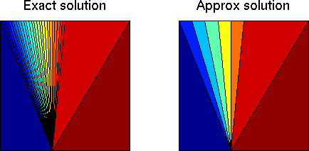
 Figure 1a: Approximation of a Riemann solution in the xt-plane. |
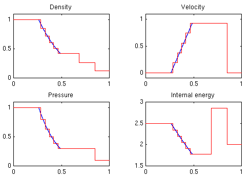 Figure 1b: Approximation of a Riemann solution |
The front tracking method for scalar problems can be extended to hyperbolic systems of the form
To this end, we need to change the viewpoint slightly. As in the scalar case, we approximate the initial data to yield a sequence of Riemann problems. However, it is not possible in general to use piecewise linear flux functions. Instead we reconsider the scalar approach. Looking at Figures 1 and 2 in that section, we see that approximating the flux function can indeed be viewed as a discretization of the solution of the Riemann problem. That is, shocks are kept, while rarefaction waves are approximated by a step functions. An example of a discretized Riemann solution is shown in Figure 1.ut + f(u)x = 0, u(x,0) = u0(x).
 Figure 1a: Approximation of a Riemann solution in the xt-plane. |
 Figure 1b: Approximation of a Riemann solution |
By adopting this point of view, it is possible to generalize the front tracking method to systems, see for instance Risebro [1]. The solution of a Riemann problem
consists of constant states separated by elementary waves (rarefaction waves, shock waves, and contact discontinuities). We approximate the Riemann solution by a step function, that is, we keep the shocks and the contact discontinuities, while rarefaction waves are approximated by a step function. In state space, the rarefaction curves are discretized whereas the shock curves remain unchanged.u0(x) = uL, if x< 0
u0(x) = uR, if x> 0
Now the global solution can be established by solving Riemann problems and tracking fronts as for the scalar case. By approximating Riemann problems by step functions, we ensure that the solution remains piecewise constant. However, it is now possible that the number of fronts may increase infinitely. To avoid this, we have to introduce some kind of data reduction in the Riemann solver, see for instance Langseth [2].
The description of the front tracking method is not complete before we explain how to impose boundary conditions in the method. A boundary can be represented by a front object with a special tag indicating that the object is a boundary. This issue is discussed in the section on implementation. However, how to resolve a possible collision at the boundary must be discussed further.
There are three kind of boundary conditions that may be imposed for any system
The four examples are of the Euler equations and show the solution in the xt-plane. Shock fronts are shown as red, contact discontinuities as green, and rarefaction fronts as blue. The boundary is in magenta. Figure 2 to 5 clearly demonstrate the complexity of the tracking part in the algorithm.
The code used for generating the examples below will soon be available on this site.
Example 1. A so-called explosion problem with simple outflow (or absorbing) boundaries. For |x|< 0.1 the pressure and density is equal 1.0, and for |x|>0.1 the pressure is 0.1 and the density is 0.125. The velocity is zero everywhere. The initial problem consists of two Riemann problems; each giving a shock, followed by a contact discontinuity and a rarefaction. After a short period the two rarefaction waves, which are of different family, will interact to form a new rarefaction waves that overtakes the contact discontinuities. Figure 2 shows the fronts up to time 1.0. See also the animation of the solution.
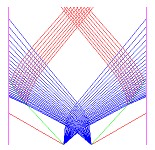 Figure 2: Example 1. |
Example 2. In the next problem we impose reflective boundary conditions to the problem in Example 1. The two fast shocks reflect at the boundary and passes through the rarefaction fans. The rarefaction wave reflects at both boundaries. (Here we have used fewer fronts in the approximation of the two rarefaction waves). The solution up to time 1.0 is shown in Figure 3.
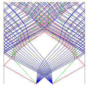 Figure 3: Example 2. |
Example 3. In the next problem we impose inflow (or Dirichlet) boundary conditions, that is, we fix the value at the boundary. The pressure is initially 0.4 and the density 1.0 everywhere. The velocity is -2.0 at the left boundary, 2.0 for x<0, -2.0 for x>0, and 2.0 on the right boundary. The Riemann problem at the origin gives two shocks propagating outwards. The Riemann problem at each boundary gives a rarefaction wave propagating inward. When the shock wave hits the rarefaction it produces a shock wave, a contact discontinuity, and a rarefaction. The solution up to time 1.0 is shown in Figure 4.
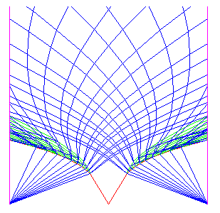 Figure 4: Example 3. |
Example 4. In the last example we impose periodic boundary conditions. The pressure initially 0.4 and the density 1.0 everywhere. The velocity is 0.0 for x<0 and 2.0 for x>0. This gives two initial Riemann problems, one at the origin and one at (say) the left boundary. The Riemann problem at the origin produces two rarefaction waves. The Riemann problem at the boundary produces two shock waves that propagates with positive wave speeds, and are therefore inserted at the left boundary. The fastest rarefaction wave leaves the right boundary and enters the left boundary before it overtakes the slowest shock. The fastest shock overtakes and interacts with the slower rarefaction. The solution up to time 1.0 is shown in Figure 5.
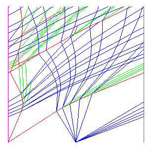 Figure 5: Example 4. |